
Note: I am continuing to make small updates to this page as I discover improvements to this technique.
I wrote up my bat detector design, the BatGizmo, in a previous blog. I noted there that it has two microphones and two independent signal processing channels. This allows for stereo bat detection. More importantly, it also allows for some interesting signal processing techniques including adaptive beamforming, outlined in this article.
There is a list of abbreviations at the end of this blog.
What is Adaptive Beamforming?
An interesting application for a bat detector with multiple microphones is beamforming. Beamforming is a method of combining the signals from multiple microphones, using different weights and delays, in such as way that the signal from a particular direction is favoured, and signals from other directions are attenuated. This is similar to the way a conference room phone can reinforce the sound from a single speaker in the room, and sound cancelling headphones can cancel unwanted sound.
A major benefit of beamforming in the field of bat detection is to maximize the strength of the signal from the bat of interest based on direction of arrival, while minimising the signals from other unwanted sources. Unwanted sound sources include:
- Echoes and reverberation from the bat of interest.
- Calls from other bats.
- Other environmental noises: coughing, shuffling, passing bicycles, car ignition systems.
There is an assumption that the loudest ultrasonic sound present is the bat of interest. Clearly, this technique can result in spectrograms with improved signal to noise ratio.
Of course, bats move around a lot, often rather rapidly. To handle this situation, an adaptive beamforming method is used, so the favoured beamforming direction can track the movements of a flying bat.
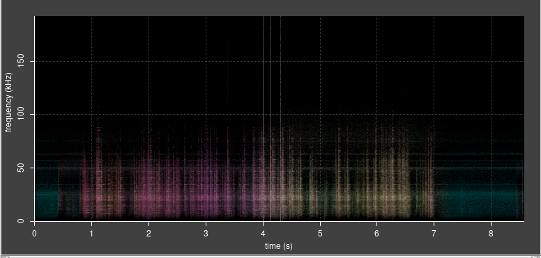
This technique also allows the directions of arrival of different sounds to be visualised in a spectrogram as a range of colours, providing an intuitive and obvious way to distinguish calls from a particular bat. This can help in confusing situations when multiple bats and their echos are present.
Note that microphone baffles are not used when adaptive beamforming is being done – these are only required for stereo recording, see the section below. A clear path between the microphone ports is best for beamforming.
Background
Audio beamforming is an established technique for passive sonar. One of its earliest applications was detecting the direction of a submarine relative to a ship, based on the sound received by an array of audio sensors in the water. It has since become increasingly common in military, business and consumer products. ChatGPT has kindly listed some examples of its application in the appendix below.
In parallel, the field of digital signal processing (DSP) has become mature and well understood, having many applications in fields such as audio, radio, and image processing. There is therefore an abundance of theoretical and practical knowledge published in various forms: reference books, academic papers, and other more informal resources on the internet.
Computing power has become extremely cheap relative to former decades, as has electronics in general.
Development software and libraries are available under licenses that allow their use at no cost in certain circumstances.
It is therefore now feasible, and in fact not too hard, for a hobbyist to build a bat detector with beamforming capabilities, as described in this article.
How it Works
The BatGizmo bat detector is described in a previous blog. It is a bat detector with two microphones and two independent signal processing channels, based on the STM32H750 microcontroller (MCU). The MCU includes an ARM Cortex-M7 core that can run at up to 480 Mhz. This much more processing capacity than is needed for a basic microphone, even running at ultrasonic sampling rates. The spare capacity is therefore available for other tasks, such as digital signal processing, which can be conveniently be built on the freely available CMSIS DSP library.
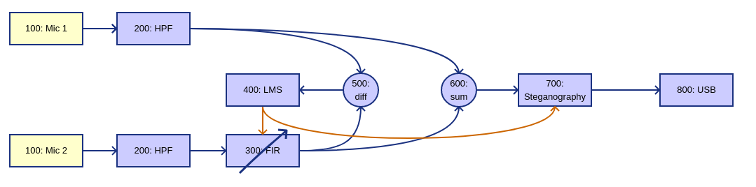
The signal path is broadly from left to right:
100: Each microphone signal undergoes analogue conditioning before being sampled by an ADC within the microcontroller. Raw signal data is processed in frames (batches of 384 samples per channel) for efficiency.
200: The digital signal passes through a second order high pass IIR filter set at 8 kHz, to remove any DC offset and attenuate environmental sounds that aren’t related to bats. It has been pointed out to me that IIR introduce phase distortion, and so a linear phase FIR might be better suited. This is a valid point. For the moment I am retaining the IIR filters, since they are relatively cheap in terms of processor load. Both the IIR the LMS-FIR filter are linear so the LMS-FIR should compensate for IIR phase distortion. I might review this again later.
300: Channel two is passed through a FIR filter whose job is to transform channel two so that it matches channel one as closely as possible. This is achieved over time as described below. The FIR coefficients are initialized so that the filter starts off by generating an output identical to its input.
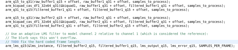
400, 500: Both channel signals are compared (subtracted) and the error signal used to drive a Normalized Least Mean Square (NLMS) algorithm. The NLMS algorithm incrementally adjusts the FIR coefficients to minimize the error. Therefore, over time, the FIR models the difference in the audio signal between the two microphones. The difference is primarily a delay, resulting from the time it takes for the sound to travel between the two microphones. NLMS is preferable to LMS, as it can model the channel difference over a wide range of audio levels.
600: Channel one and filtered channel two are added, sample by sample. Channel two has been adapted by the filter to match channel one as closely as possible, which includes eliminating any time/phase difference between them. So, the signals being added are in phase – interference between the signals is always fully constructive at this point, based on the strongest component in the signal.
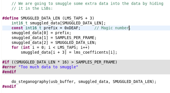
700: It’s useful for offline analysis software to know the FIR coefficients that were in use at a particular time. Ideally this would be included as an additional data channel. However, this would be likely to confuse standard software packages and apps, and in any case, almost the entire bandwidth of full speed USB is required for audio data samples at 384 kHz. Therefore, this design takes advantage of the fact the that least significant bit of the 16 audio data is typically noise, and uses a simple steganography technique to smuggle the coefficient data through the regular signal stream. The resulting bit rate for the coefficients is of course low, but the coefficients change slowly, so this is acceptable. In practice it is invisible in spectrograms.
800: The resulting signal stream is presented as a USB audio (AUC1) endpoint, which can be accessed by standard software and apps.
Analysis
BatGizmo generates USB audio data which apps and software typically save as .wav files. These files can be processed in the usual way into spectrograms, using software such as Audacity. However, the raw data also contains additional data resulting from the adaptive beamforming process, relating to the direction of arrival of the bat calls.
This beamforming data can be extracted by the reverse process of the LSB steganography described above, by analysis software that is aware of it. I have added this support to batogram, my open source bat spectrogram project.
Here is the processing it does to extract and use the additional data:
- Examine an initial chunk of raw data to see if a magic number is encoded in the LSBs of consecutive samples.
- If so, use this knowledge to extract the adaptive beamforming coefficients for the entire input data.
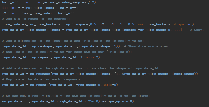
- The coefficients are used to derive a colour in the spectrogram. There is no obvious way to map N coefficients to 3 RGB colour coefficients. I chose therefore to use Principal Component Analysis to do dimension reduction from N to 2. This preserves maximum variation in the data, ensuring maximum colour contrast in the spectrogram. The two colour components and the signal intensity can be mapped to colour using, for example, MSLuv. The actual colours that result have no significance other than a way to correlate different chirps in the same spectrogram.
The Python numpy library provides a convenient way to implement this.
Results
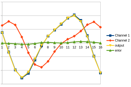
This is all very well, but how does it work in the real world with actual bat calls?
Frustratingly, I finished building the adaptive beamforming feature in November 2023, some time after all sensible bats have gone into hibernation for the winter. So I can only test it with artificial sounds such as jangling keys.
Results based on key jangling are promising. I am looking forward to testing it out with real bats in spring 2024
Future Improvements
Only two microphones were used in this proof of principle implementation. But, MEMS microphones are cheap, as electronics. The STM32H750 microcontroller I am using has unused ADC channels and plenty of unused processing power. Directional resolution could be much improved by having more microphones. Even just an increase to three should result in a real improvement.
Stereo Detection
The most obvious application for a two channel bat detector is the ability to record bats calls in stereo. When heterodyned in stereo, the sound of these noctules flying around my local park is rather wonderful. More practically, it also gives the listener a cue where to look to see the bat.
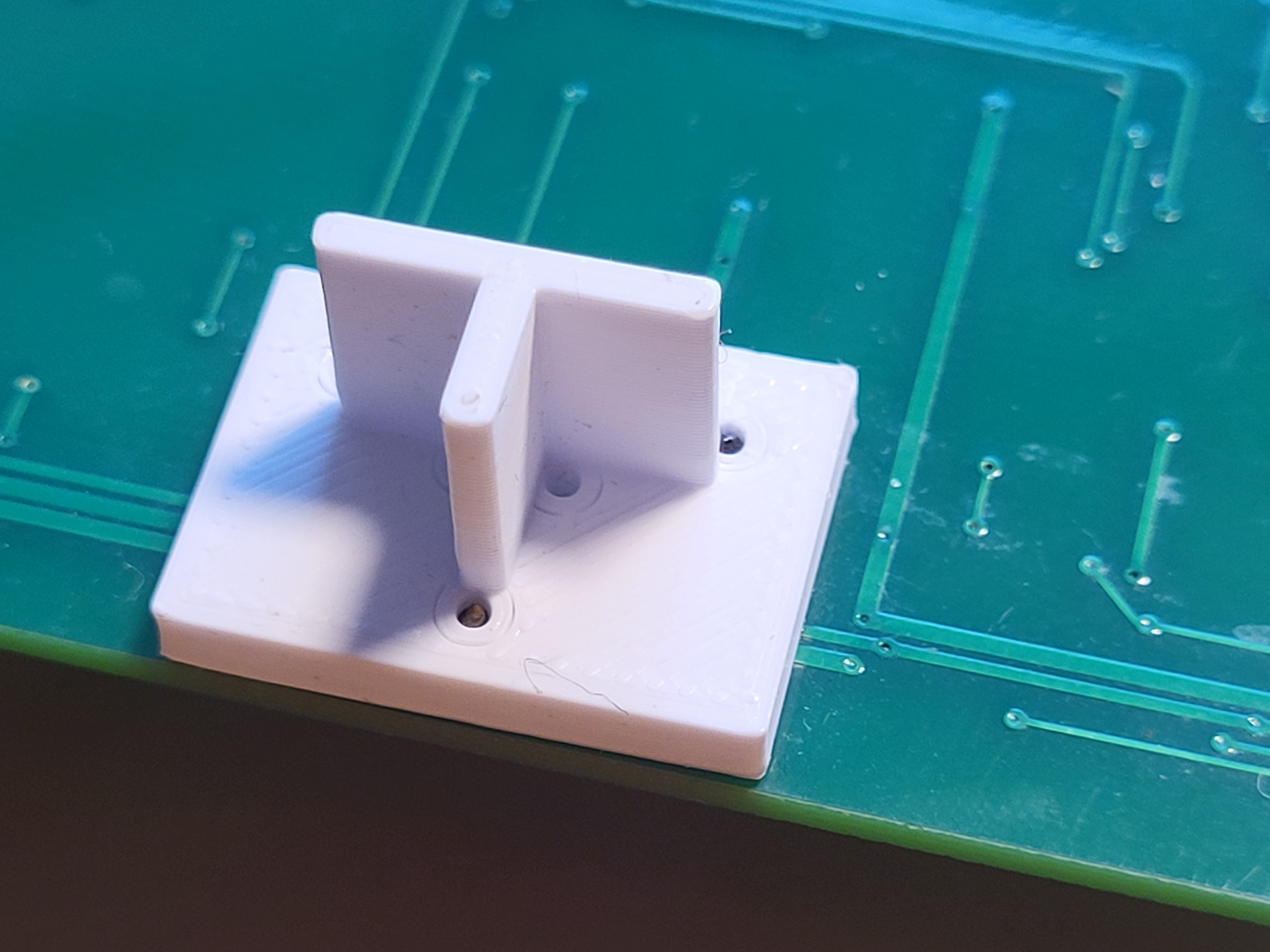
To achieve stereo separation between the two channels of the BatGizmo, some kind of baffle is needed, as shown in the picture. The baffles mean that the left microphone picks up sound most strongly from the left; the right microphone from the right. The baffles are also an effective acoustic horn, increasing signal intensity without any corresponding increase in detector self noise.
A limitation of stereo bat detection is the finite bandwidth of USB audio, based on the “full speed” USB spec as most commonly implemented in Android tablets and phones. This limits stereo detection of 16 bit data to a 192 kHz sampling rate, while 384 kHz is possible in mono mode.
Appendices
More Information
This paper outlines audio beamforming based on LMS.
Microphone arrays for studying echolocation.
TLAs
ARM – Acorn RISC machine. A processor core designed in the 1980s in Cambridge, living on in most mobile phones and many other products.
DSP – Digital signal processing.
FIR – Finite impulse response. This is one of two common types of filter used in DSP.
HPF – High pass filter. A filter that progressively attenuates signals below a certain cut off frequency.
IIR – Infinite impulse response. This is one of two common types of filter used in DSP.
LMS – Least mean square. This is an algorithm commonly used in DSP to iteratively adapt a FIR filter to model a particular situation, as the signal delay between two microphones. Another application is sound cancelling headphones.
LSB – Least significant bit. When a binary number is written out in the usual way, this is the value of the right-most digit.
MCU – Microcontroller unit. This is an integrated circuit compromising a processing core, some memory, and lots of peripherals for interfacing with the outside world. The BatGizmo uses the STM32H750
PCA – Principle component analysis. A method for reducing the number of dimensions in a model to make things more manageable, while preserving as much variation as possible.
TLA – Three letter acronym. More correctly, in most cases, they are three letter abbreviations.
USB – Universal serial bus. A general purpose standard that allows many different computer peripherals to be plugged together with standard connectors. Like anything designed by a committee, is unbelievably complex and impenetrable. Sadly it is an established fact of life.
Applications of Audio Beamforming
In the words of ChatGPT:
Audio beamforming is a signal processing technique that focuses sound in a specific direction, allowing for targeted listening or transmission. Here are some examples of applications of audio beamforming:
- Video Conferencing Systems:
- Beamforming microphones are often used in video conferencing systems to enhance the audio quality during virtual meetings. By focusing on the speaker’s voice and reducing background noise, beamforming helps improve communication clarity.
- Voice Assistants and Smart Speakers:
- Devices like smart speakers and voice-activated assistants use beamforming to better understand and respond to user commands. This helps in isolating the user’s voice from ambient noise, leading to more accurate and reliable voice recognition.
- Teleconferencing Systems:
- Audio beamforming is crucial in large meeting rooms or auditoriums where multiple speakers may be present. Beamforming technology helps capture the voice of the person speaking and reduces the pickup of unwanted background noise.
- Hearing Aids:
- Beamforming is employed in advanced hearing aids to enhance the wearer’s ability to focus on specific sounds, such as conversations, while suppressing background noise. This improves the overall listening experience for individuals with hearing impairments.
- Automotive Systems:
- In-car communication systems and hands-free calling benefit from audio beamforming to isolate the driver’s voice from road noise and other sounds within the vehicle. This contributes to a safer and more efficient driving experience.
- Security and Surveillance:
- Audio beamforming is used in security applications to precisely capture and analyze sounds in a specific direction. This can be valuable for detecting unusual noises or identifying specific sounds in surveillance scenarios.
- Public Address Systems:
- Beamforming technology is applied in large venues, such as stadiums or concert halls, to focus the audio output on specific areas. This ensures that the sound is delivered clearly to the intended audience without causing disturbances in other areas.
- Home Entertainment Systems:
- High-end soundbars or home theater systems may utilize audio beamforming to create an immersive audio experience. By directing sound to specific locations, these systems can simulate surround sound without the need for multiple speakers.
- Robotic Systems:
- Audio beamforming can be integrated into robotic systems for better human-robot interaction. Robots equipped with microphones and beamforming capabilities can focus on and respond to human voices even in noisy environments.
- Industrial Applications:
- In industrial settings, audio beamforming can be used for monitoring and quality control. For example, it can help detect anomalies or specific sounds indicative of machinery malfunctions.
These examples demonstrate the versatility of audio beamforming across various domains, improving communication, interaction, and overall user experience in diverse applications.

4 responses to “Adaptive Beamforming for Directional Bat Detection”
Nice article like the others.There’s a small typo :200: The digital signal passes through a second order
lowhigh pass IIR filter.Did you tried without the “baffle”?To me is make the job of the FIR/LMS filter more difficult as they are based on phase variation. It should be easier to compare 2 signals with the same amplitude but with just a phase variation.Keep up the good job. Your articles are very interestingThanks! I’ve fixed the typo you mention. Yes indeed, I don’t use the baffle in adaptive beamforming mode, for the reason you give, it just confuses things. I’ve added some text to make that clearer.
Impressive! you explain things very well. I like the reference to hearing aids too, that is something I have told my audiologist.
There’s an idea for an rather niche product there.