Updated on 2026-02-13 with the quarter wave stub tuned to 20 kHz to markedly reduce an undesirable microphone sensitivity spike. The result is a very useful flattening of the MEMS microphone frequency response.
Over recent years, a number of low to medium cost bat detectors have become available, including commercial products, open source designs and build-it-yourself projects. They are typically based on MEMS microphones. These are ubiquitous in mobile phones and other devices with integrated microphones. They have the benefit of being low cost, with very useful sensitivity into the ultrasound region where bat calls occur, and in some cases have other benefits such as in-built waterproofing and vibration compensation.
They can also have less desirable properties, some of which are outlined below, together with measures that can be taken to reduce their impact.
Frequency Response
A smooth frequency response is important for undistorted spectrograms, helpful if you want to estimate the frequency of maximum energy, and to minimize overloads and dead bands.
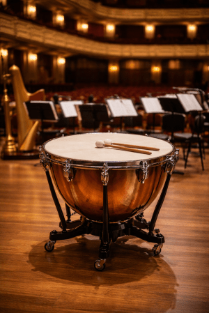
Unfortunately MEMS microphones present some challenges in this regard. They typically have a far from even frequency response, often with marked peaks and troughs of sensitivity. This varies with make and model of microphone, but is present in all to some extent. The cause is resonances resulting from the closed volume air and the presence of one or more diaphragms. This is somewhat analogous to timpani as played in a symphony orchestra, which are tuned to a basic pitch by adjust the tension in the head, resulting in a fundamental resonance and a complex series of overtone resonances.
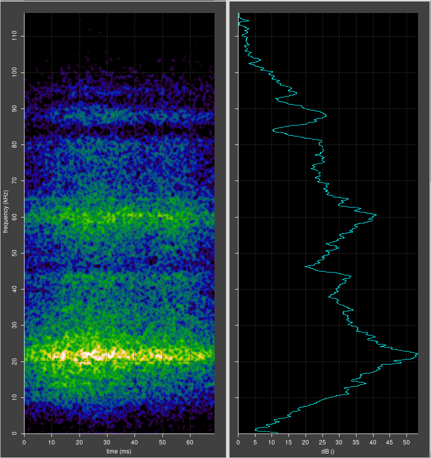
An example of the uneven frequency response is shown below.
Sensitivity
Another challenge is the impedance mismatch between free air and the microphone. Analogous to impedance in electrical circuits, a good acoustic impedance match is important for efficient energy transfer from sound waves to movement of the microphone diaphragm. The acoustic impedance of free air is low, but the impedance of the diaphragm is high, result in a good proportion of the sound energy arriving at the microphone being reflected back out of the microphone, without contributing to movement of the diaphragm.
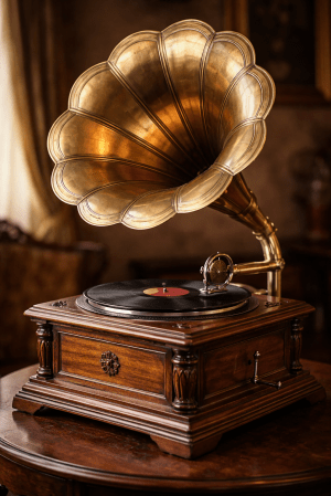
This problem can be much reduced by fitting a horn to the front of the microphone, similar to the horn on an old fashioned gramophone. A common design is an exponential horn with a narrow throat matching the microphone port diameter, and a flared mouth. The horn approximately matches the low impedance of free air with the high impedance of the microphone, resulting in much more efficient energy transfer and therefore greater sensitivity to sound.
Quick measurements on the bench suggest that an increase of sensitivity in the range 6 to 9 dB is possible, with very little change in the noise background. This is definitely worth having, but there is a price to be paid – the presence of the horn makes the microphone somewhat directional. However, as long as the mouth of the horn is less than or comparable with the wavelength of the sound of interest, the directional effect is minimal. In some situations it might even be useful.
A Practical Horn
Acoustic analysis of horns is complex. Fortunately, it is relatively simple to design a range of horns, 3D print them, and experiment to decide what works best.
Good news: there is excellent free software that can be used for designing a horn. I started off using FreeCAD, which is a visual point-and-click designer for 3D objects. It has good features, but ultimately I found that it was a little unintuitive to use and also had some bugs. So, I changed to using the CadQuery Python module with CQ-editor development environment. If you can describe the shape you want in words and you have some basic programming skills, this is the approach I recommend. If you get stuck, ChatGPT is pretty helpful.
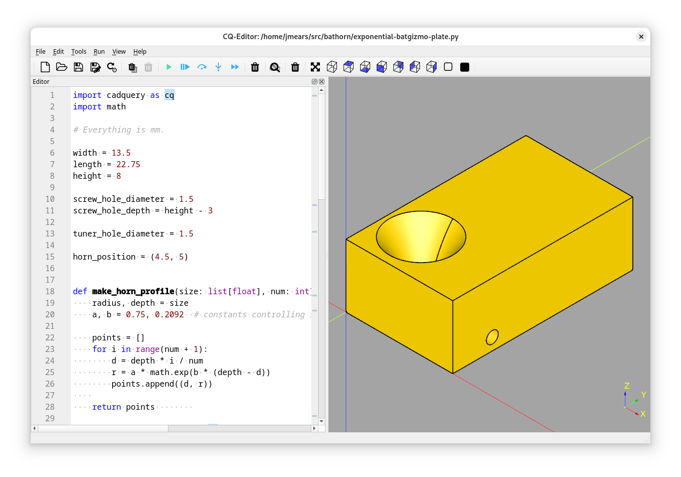
The resulting STL file can be read into whatever slicer software you use (I use Cura) and used to print the horn. My 3D printer is a basic model of Creality Ender which is fine for this.
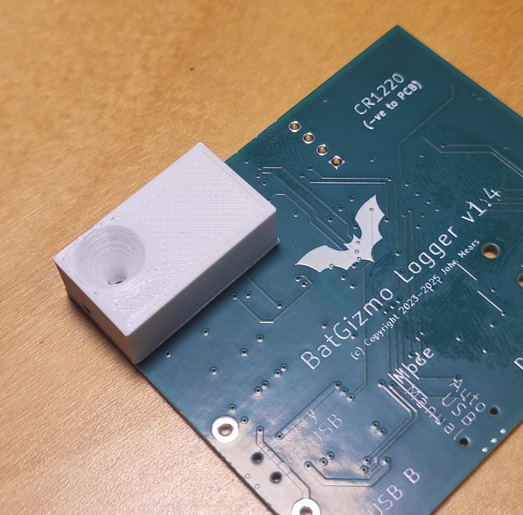
My design comprised:
- A rectangular block designed to sit on the non component side of my bat detector PCB.
- An exponentially flared hole through the block, with a throat of 1.5mm, a mouth of 8mm and a depth of 8mm.
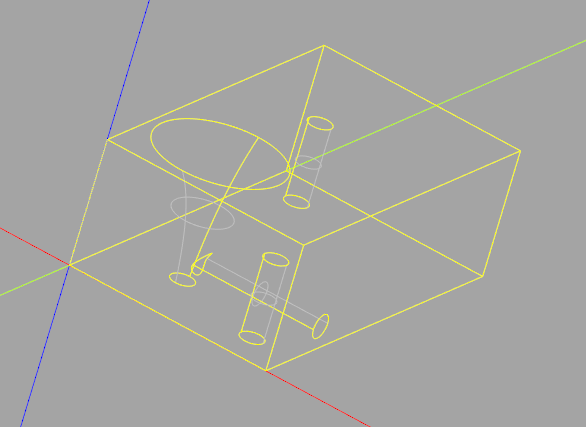
- Concealed holes allowing it to be attached to the PCB with two small self tapping screws.
- A side vent from the throat of the horn accepting a 1.6 mm grub screw. More on this below.
This took about 12 minutes to print, and was pretty much right first time. I used a 1.5mm drill bit held in a pin vice to clean out the side vent, and screwed in a grub screw using a 0.7mm hexagon key. This has to be done carefully – the hexagon key is easily bent, and it is easy to drop things on the floor, only to be found next time you vacuum.
Quarter Wave Stubs
Why did I include the side vent? I wanted to experiment with adapting the resonances of the horn and microphone system with a quarter wave stub. Use of quarter wave stubs is well established in other fields, such as radio and loud speaker design.
The basic idea is to add a closed ended side tube (a stub) to a waveguide, in this case, near the throat of the horn. In my design, the side tube is closed by a grub screw, which can also be used to determine the length of the side tube. If it is screwed right in, the result is a plain horn. If it is unscrewed by a little distance, the resulting side tube acts as a quarter wave stub by providing sound waves with two paths to the microphone:
- Directly down the horn from the mouth to the throat.
- The same, but with a detour into the stub, being reflected back out again by the closed end of the stub.
The difference in path is length twice the length of the stub. If that length is chosen to be a quarter of the wavelength of interest, the two paths for sound differ in length by half a wavelength, destructive interference results, and sound of that wavelength is attenuated. This could be useful for reducing a sensitivity peak of the microphone.
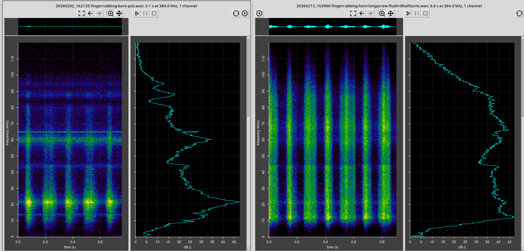
The quarter wave stub indeed results in an attenuation of audio at a frequency defined by the length of the stub, as shown below.
Conclusions
- A simple horn fitted in front of a MEMS microphone amplifies the sound very usefully, with little change in the background noise. Directionality is increased somewhat, but it can be minimised.
- There was also a useful spreading of the microphone resonance peaks.
- An adjustable quarter wave stub can be tuned to attenuate a specific frequency of sound, in this case the sensitivity spike at 20 kHz. This is been successful as can be seen from the graphs above.
Of course these measurements are far from rigorous and scientific, but provide a strong indication that a horn can be useful in increasing sensitivity and somewhat flattening the microphone response.
Appendix – Source Code
import cadquery as cq
import math

# Everything is mm.

width = 13.5
length = 22.75
height = 8

screw_hole_diameter = 1.5
screw_hole_depth = height - 3

tuner_hole_diameter = 1.5

horn_position = (4.5, 5)


def make_horn_profile(size: list[float], num: int) -> list[tuple[float, float]]:
    radius, depth = size
    a, b = 0.75, 0.2092  # constants controlling shape

    points = []
    for i in range(num + 1):
        d = depth * i / num
        r = a * math.exp(b * (depth - d))
        points.append((d, r))

    return points

def create_horn(base_solid: cq.Solid, position: tuple[float, float]) -> cq.Solid:
    top_z = base_solid.faces(">Z").val().BoundingBox().zmax
    x, y = position
    profile = make_horn_profile((4, 8), 5)
    print(profile)

    wp = (
            cq.Workplane("XY")
            .workplane(offset=top_z)            # Horizontal workplane at top face of the block.
            .center(*position)                  # We will transform/rotate about this point.
            .transformed(rotate=(0, 90, 0))     # Workplane is now vertical facing right: X is now down.
            # Draw the profile.
            .moveTo(0, 0)
            .lineTo(*profile[0])                      # Towards the left face
            .spline(profile)
            .lineTo(height, 0)                       # Back right
            .close()
            .revolve(360,                       # Revolve around the transformed X which is down.
                     axisStart=(0,0,0),
                     axisEnd=(1,0,0))
    )

    return wp

def create_block() -> cq.Solid:
    (x, y) = horn_position

    block = (
        cq.Workplane("XY")
        .box(width, length, height, centered=(False, False, False))
        # Move the origin to the bottom left:, position: (float, float)
        #.translate((width/2, length/2, height/2))

        # Screw holes:
        .faces("<Z")
        .workplane()
        .pushPoints([
            (width - 2.75, -2.75),
            (2.5, -20),
        ])
        .hole(diameter=screw_hole_diameter, depth=screw_hole_depth)

        # Work from the end: create a tuning hole.
        .faces(">X")
        .workplane()
        .center(y, 1.5)
        .hole(diameter=tuner_hole_diameter, depth=width-x)
   )

    return block

block = create_block()
horn = create_horn(block, horn_position)
block_with_horn = block.cut(horn)
show_object(block_with_horn)

# cq.exporters.export(block_with_horn, 'exponential-horn-block-2.stl')

One response to “Horns and Quarter Wave Stubs for Flattening MEMS Microphone Frequency Response”
Dear John
I have just made some comments on your 3D horn design via the Bat Call Analysis Workshop page. The comments are there but I could not successfully upload the image of the gain curve.