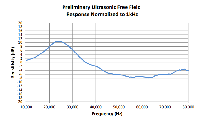
The Knowles SPU0410LR5H-QB microphone is inexpensive and well suited to detection of ultrasound. Knowles’ own published data shows sensitivity up to 80kHz, and my experience is that it can detect ultrasound at over 100 kHz.
This microphone is a good candidate for home projects. However there is one big challenge for a hobbyist – how to make connections to it. Its package is very small, and connections have to be soldered to tiny contacts which are located beneath the package, inaccessible when the device is on a PCB.
One solution to this is to buy the microphone presoldered into a breakout board that provides through-hole connections, such as this one sold by MicBooster.com (FEL Communications Ltd). This certainly solves the problem and is good enough for a prototype. But it would be nice to avoid having an additional breakout PCB.
This blog describes the method I used to solder this microphone to a PCB, including some pitfalls to avoid and things I would do differently next time.
Equipment
Here’s what I used:

- A miniware MHP30 hotplate preheater, obtainable via the usual online suppliers.
- A soldering iron with a smallish chisel shaped bit.
- 63/47 leaded solder, which has a low melting point and flows well.
- Isopropyl alcohol.
- Liquid flux.
- Tissues, cotton buds etc.
- A PCB with pads pre-tinned with leaded solder (PCBWay did a good job).
- A microphone and ideally a few spares. They are not expensive.
- A multimeter.
- Tweezers, small screwdriver, straight edge to aid placement, etc.
PCB Footprint
PCB footprints for this microphone can easily be found online. I took one of these and imported it into Kicad, the free CAD software I generally use for schematic and PCB design. I modified it, lengthening the pads to extend beyond the microphone package, allowing more options for getting solder to flow under the package. In fact I think this was not necessary, though it made it easier to tin the solder pads initially and did no harm.
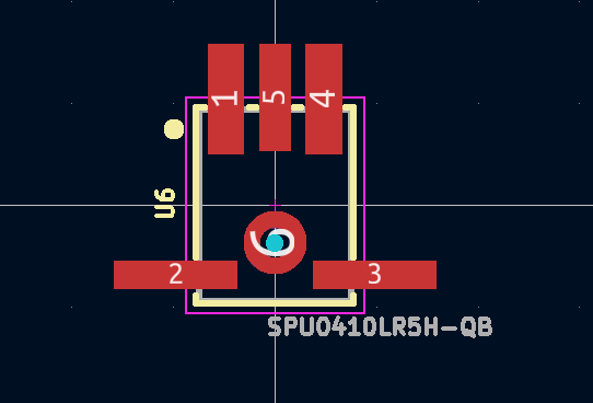
If I do this again, I will increase the drilled hole size in the footprint to 1mm and make sure it is not plated through, to make alignment less critical and reduce the chance of it clogging with solder or flux during the process below.
Tinning
Each pad that you want to solder on the PCB and on the microphone itself needs tinning, so that a (roughly equal height) low hump of solder remains on each pad.
- Clean the pad with a tissue or cotton bud soaked in isopropyl alcohol (IPA). Take great care not to clog the microphone port by getting IPA in it – squeezing as much of the the IPA from the tissue or bud as you can before you use it.
- Apply minimal flux. Take extreme care not to let flux clog the microphone port, particularly if your flux is liquid. The best way I found is to soak a very small amount of flux into a tissue, squeeze out as much as you can, and then wipe the pads with that issue, keeping it clear of the port.
- Melt a small amount of solder onto the soldering iron, and carry that to the pad by touching the iron on the pad. The pads are close and you will probably end up tinning two or more pads at a time. That’s OK as long as no bridges remain.
I found that I could conveniently hold down the microphone on my bench with a small screwdriver or similar, while using a finger and nail from my other hand to guide the soaked tissue over the pads.
To repeat, there main risk when tinning is that flux or IPA could flow into the microphone port, which would be a disaster. Don’t let that happen.
For simplicity and to avoid the risk of clogging the microphone port, I decided not to tin the circular pad around the port itself.
I manually drilled out the microphone port in the PCB to 1mm, to reduce the risk of clogging. Next time I will update the PCB footprint to a 1mm non-plated-through hole to avoid the need to manually drill.
Placement
Place the microphone on the PCB, lining it up with silkscreen lines on the PCB so that the margin is as nearly equal all round as you can manage. This is pretty ticklish, and one good sneeze will have you crawling around on the floor trying to find the microphone, probably unsuccessfully (I lost one this way). I found the best way to position the microphone was to push a straight edge up against it, such as a piece of card or another PCB.
Heating
Transfer the PCB onto the preheater, taking care not to disturb the position of the microphone. I needed to weight the PCB with coins so that it balances on the heater, as shown.
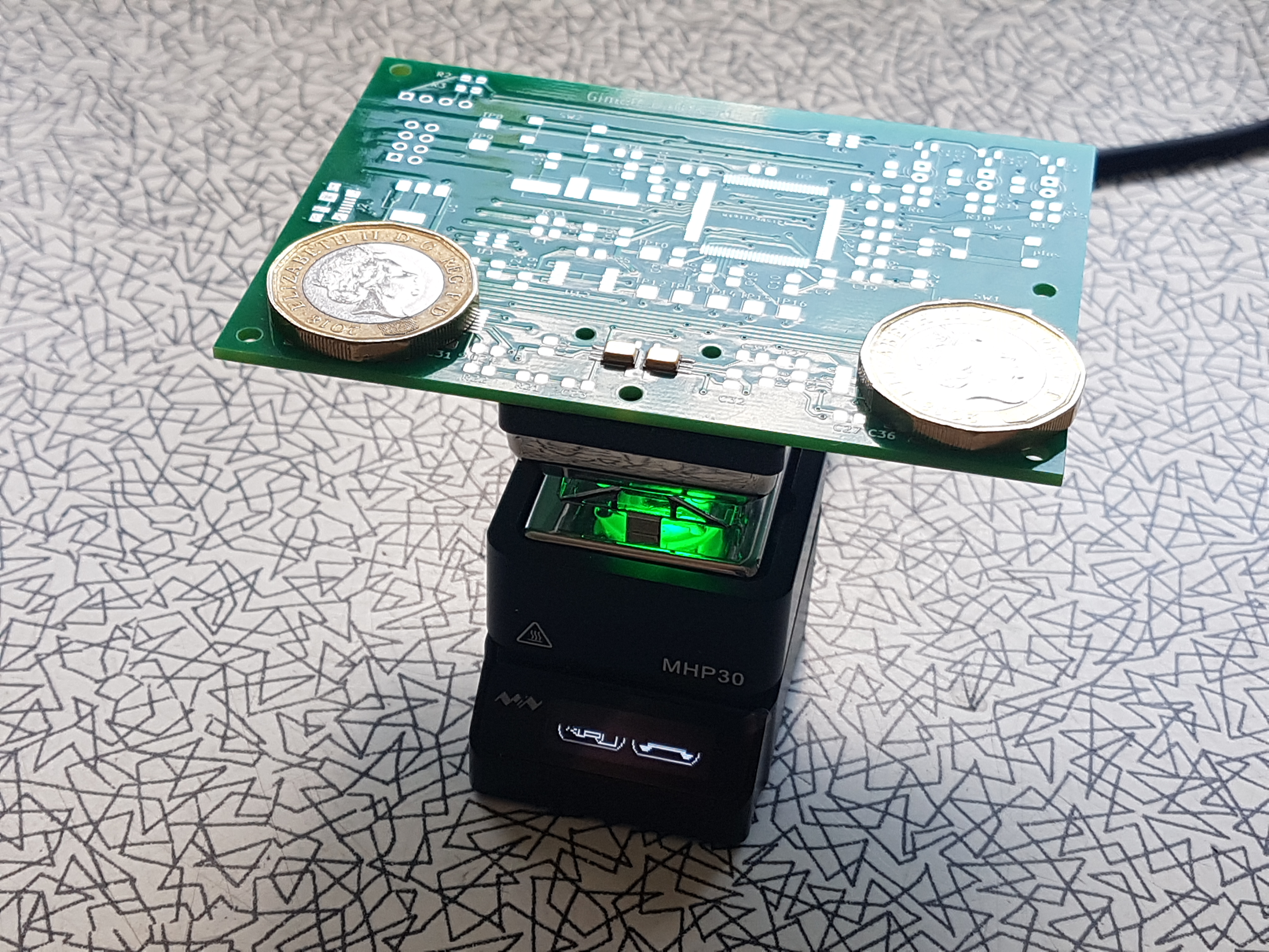
I used the lowest standard heat setting of the MHP30, by pressing button A (back left) just once. It took about a minute to heat the PCB up to 220C, and a little smoke was generated. It was just possible to see that the solder was fluid. Once it reached temperature, I counted slowly to 10, then unplugged the heater and waited for it to cool.
Finally, I checked the connections using a multimeter set to a high resistance range. You can check each connection by touching the microphone package with one meter probe, and touch an appropriate PCB pad with the other. You should see finite resistances, which may be high, but not infinite.
If any connections are open circuit, you can try simply reheating the PCB. If this does not work, you probably need to apply a little more solder on each pad when initially tinning.
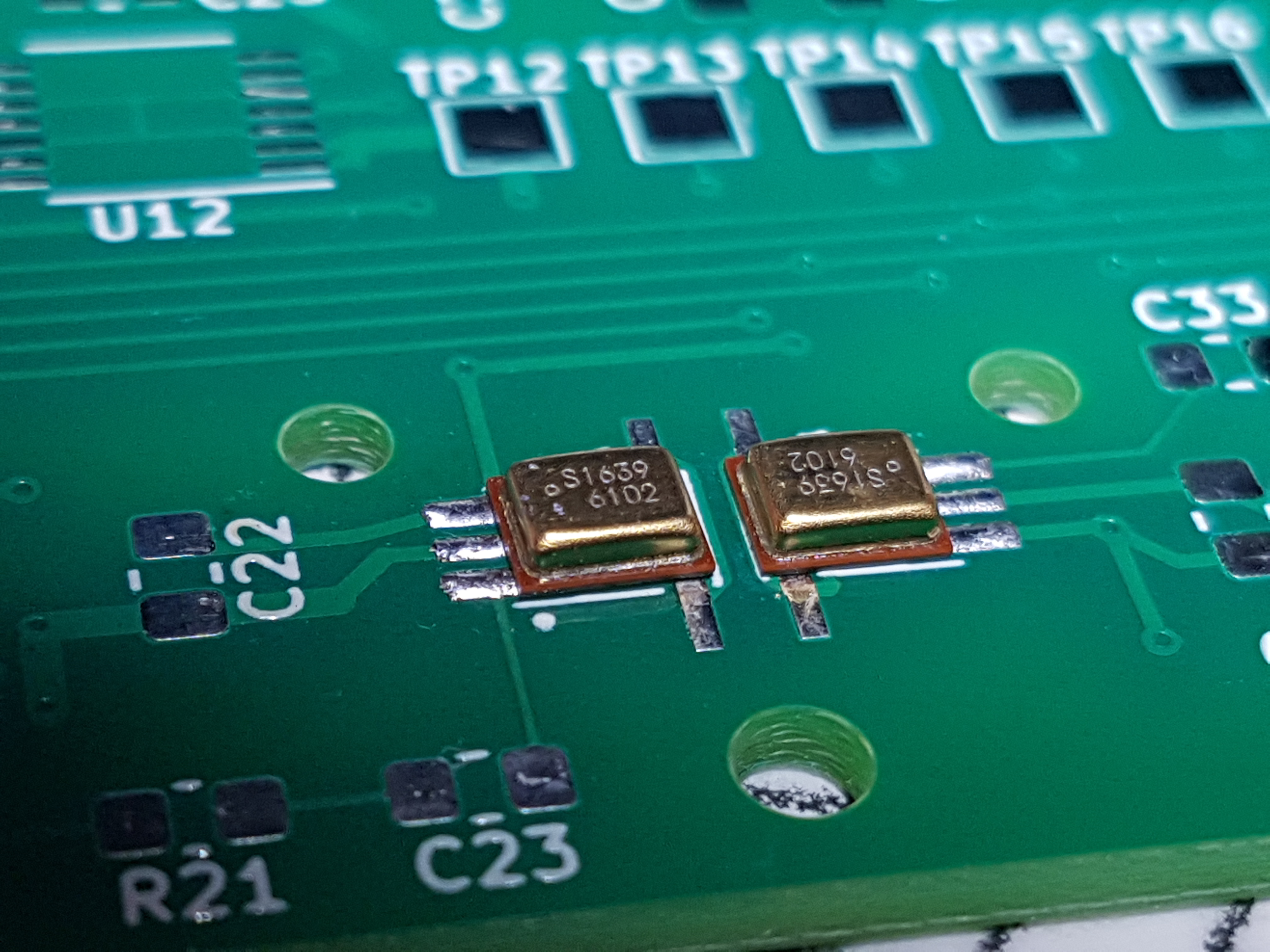
End Result
The end result is quite neat, though I say it myself. As you see, my design has a pair of microphones.